
SERPICO
It has not been long since the Raspberry PI Fondation began to distribute a new board, the PICO, based on an MCU of their own design whose heart is still a Cortex M0+ dual-core ARM processor. All the features, and the information to use it, can be found on the site https://www.raspberrypi.org/products/raspberry-pi-pico/, so I’m not here to dwell on the details.
But let’s get straight to the project, as a member of Officine Robotiche the first project I could carry out with PICO, in your opinion, could it not have been a Robot? I would say no, and I must say that I was also surprised by the characteristics of the RP2040 MCU, because it has features that are well suited to the construction of a Robot.
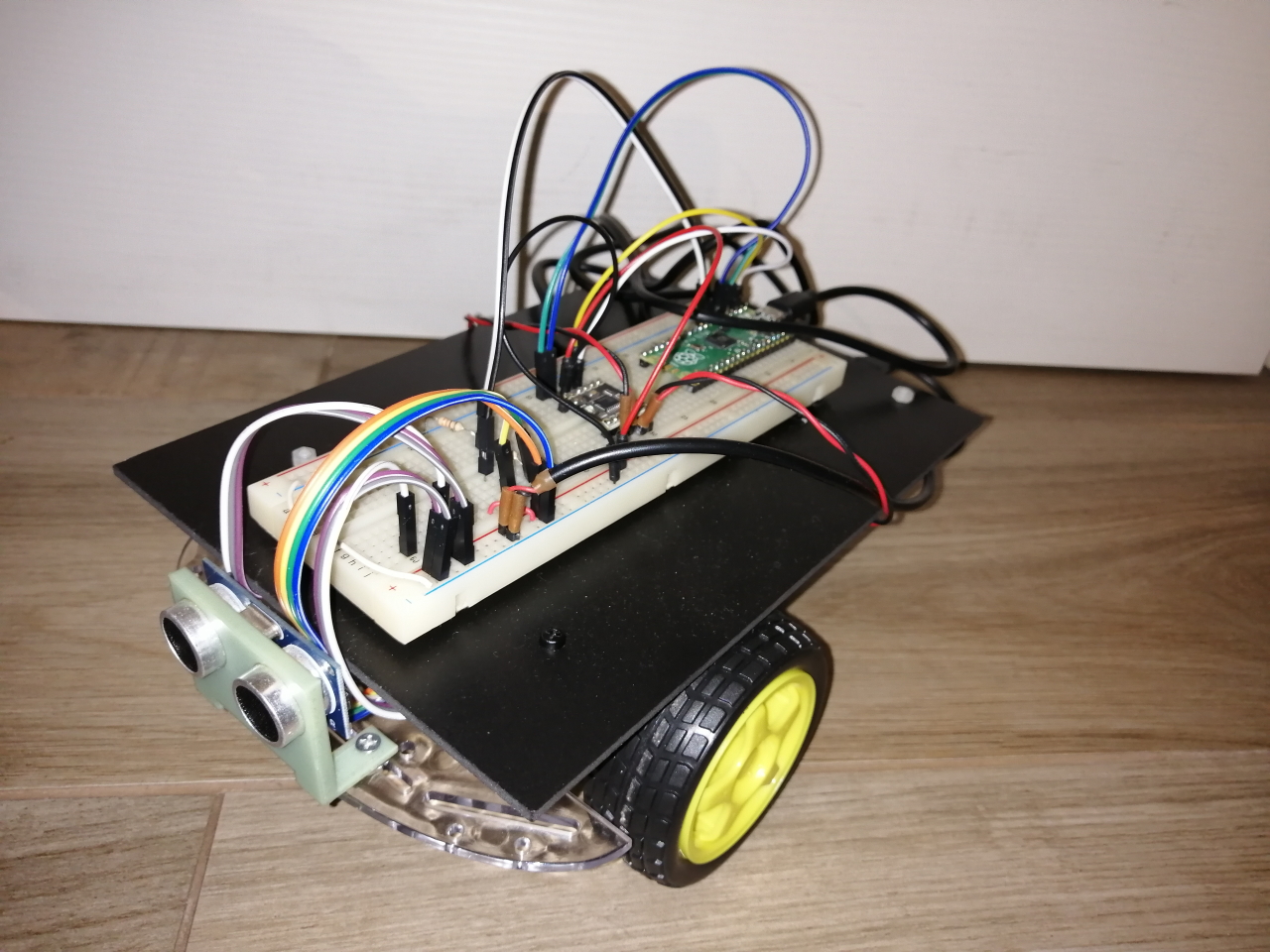
The name of the Robot is SERPICO, which as you have already understood, is nothing more than the acronym of: Studying Electronics and Robotics with PICO
All the code and other information are available in the following repository: https://github.com/bobboteck/SERPICO
La versione in italiano di questo articolo è disponibile sul sito di Officine Robotiche: https://www.officinerobotiche.it/2021/03/05/serpico/
Constructive simplicity, is the watchword
I would not want to give too many illusions with the word simplicity, so I tell you right away that you will need to use a soldering iron, but I tried to make SERPICO using the simplest I had at home, and without the need to print something in 3D. Let’s see the list of components necessary for the realization:
- Raspberry PI PICO (it seems obvious to me)
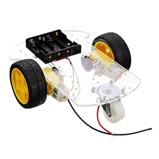
- base for Robot in kit (search for “Robot Car Chassis Kit” on the internet)
- a piece of expanded PVC or another plane equal to that of the Robot
- spacers in nylon or metal
- a breadboard for
- motors based on DRV8833
- Ultrasonic sensor HC-SR04 and relative support
- two resistors (one from … and one from …)
- wires for the connections on the breadboard
- powerbank with two outputs
- a USB cable to be cut
The kit for the base of the Robot, is a choice to make up for the classic Achilles heel for those approaching the construction of a Robot for the first time, and does not have special tools / equipment (see 3D printer, CNC, laser cutting, …).
Also on the net you can find single bases without all the kit, to make the upper top, I alternatively used a piece of expanded PVC, which can be easily cut with a cutter (please be careful anyway) and drill with a screwdriver. I used this second floor as a support for the breadboard, while on the one in the kit I anchored the powerbank.
The circuit
Assembling the circuit is very simple, after having soldered the two rows of comb connectors on the PICO insert it into the breadboard. ATTENTION!!! Check carefully the connections you are going to make on the breadboard, avoiding creating short circuits, which could damage the USB ports of your computer. A piece of advice I could give you to avoid taking any risks is to program the board before assembling the rest of the circuit, so that you can test the individual parts using an old power bank as well. Once the PICO has been programmed, first of all it will make the LED blink 5 times, this is already a good symptom that it is working.
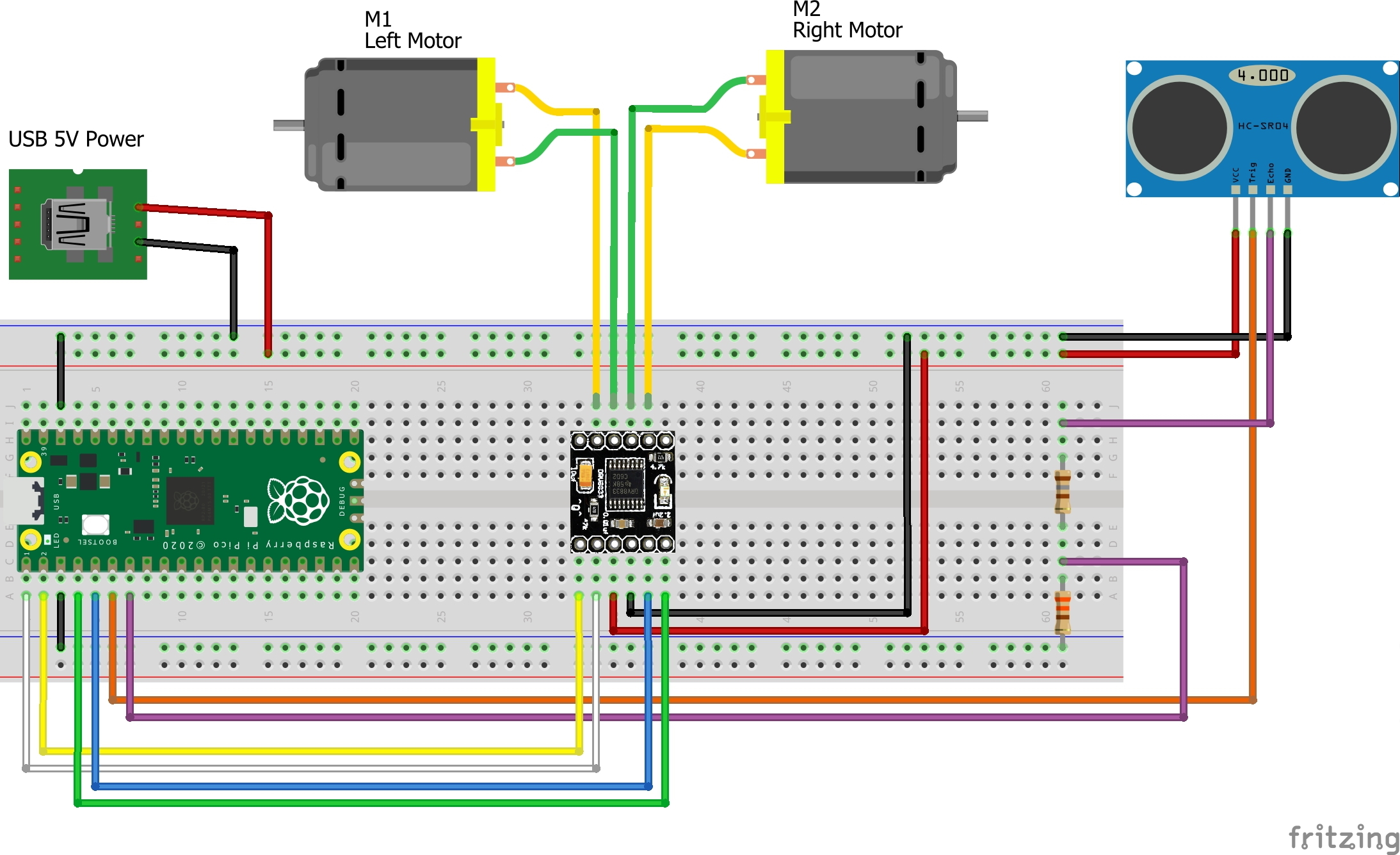
First we connect the second USB cable to one of the sides that carry the breadboard power supply, in the drawing to give the idea of what had to be done I put a micro USB connector, from which it takes the two signals of + 5V and GND. For example, I used an old USB cable with the connector broken on one side, so on the USB A side I use it to connect it to the powerbank, on the other side I cut it and took the two Red and Black wires to connect them with two pins to plug into the breadboard. The ultrasonic sensor can then be connected, as you can see from the assembly diagram, the power supply of the sensor must be connected to the 5 Volt line coming from the PowerBank. The Trigger pin can be driven directly by the PICO, while the sensor output (Echo) which also at 5 Volts cannot be sent directly to the PICO, but we use a voltage divider to make the 5 Volts become approx. 3.3. By connecting both the PICO and the 5 Volt connector to the powerbank this time, after the LED on the PICO flashes, you should hear a very slight click emitted by the HC-SR05 sensor. If there are no problems you could then connect the PICO to the PC, open a terminal on the Serial and see the measurement read by the sensor on the screen. After disconnecting the USB cables, from the power bank or from the PC, continue completing the module connections with the DRV8833 and the motors. By plugging the USB cables back into the power supply, the two wheels will start spinning, so pay attention. If the wheels are turning, congratulations, your Robot is working.
Peripherals
What I would like to highlight is one of the possibilities that the RP2040 MCU offers us, regarding the generation of PWM signals that are used to drive the two motors. In practice, the RP2040 has as many as 8 peripherals capable of generating PWM signals called Slice, each of these has two outputs, identified with letters A and B, and connected to two GPIOs. If you want to read some more details, I refer you to the article of our friend Giovanni Bernardo from Settorezero: https://www.settorezero.com/wordpress/raspberry-pi-pico-gestione-del-pwm-in-micropython/. In addition to the configuration of the various parameters, to determine the operating mode and the frequency of the signal generated by each slice it is possible to establish the polarity of the two outputs A and B. It is sufficient to set output B as inverted to have the two PWM signals in phase opposition, perfect for driving an H-Bridge in LAP mode, in this way we will have that with the Duty Cycle at 50% the motor remains stationary, while it will go at maximum speed in one direction or the other with the Duty Cycle at 0% or 100%. It is not obvious to find this mode in a microcontroller, for example in PICs it is present only in models made specifically for motor control. I only add that to obtain a frequency of 20KHz, the TOP register is set to 5000, so we could vary the register (CC), used to compare the counter value, which establishes the PWM Duty Cycle from 0 to 5000. Remembering that with 5000 we will have the maximum forward speed, with 0 the maximum reverse speed, while setting the register to half (2500) the motors will be stopped. You will also have the opportunity to experiment empirically, that it may take a value of more than 3000 to start the engine, because it is another story that maybe we will have the opportunity to deepen on other occasions.
The program
I would not go into detail on every single line of code, if you look at the complete program it is well commented and should be easy enough to read. The first lines of the main are used to configure the GPIOs used, in particular the configuration of the two Slice PWMs.
The main part of the program is all contained in the infinite loop, created with the while(1) {…} statement.
First a distance measurement is made with the HC-SR04 sensor with the usMeter() function, of which after we see some details, if the measured distance is greater than 10 cm, a simple formula is applied to set the duty cycle value PWM, to have a speed proportional to the free space in front of the Robot. Otherwise, if the distance is less than or equal to 10, the turn() function is called which stops the motors, makes them rotate in the opposite direction for a second and then stops them again.
Now let’s see how the value for the CC register is calculated. Assuming that the maximum measurable distance from the ultrasonic sensor is 200 centimeters (2 meters), that the minimum value of the CC register to move the wheels forward is 3000 and 5000 is the maximum value, for how the slices have been configured in this case, we have the possibility to exploit a variation of:
5000 - 3000 = 2000
If we compare this calculated value (2000), with the maximum number of centimeters that we have defined that we can measure (200), we have as a result 10, from these considerations we can define the following formula:
pwmDuty = (obstacleDistance * 10) + 3000
It will be sufficient to apply this value to all the CC registers, of both channels of the two Slices, to do so just use these two instructions:
pwm_set_both_levels(slice0, pwmDuty, pwmDuty);
pwm_set_both_levels(slice1, pwmDuty, pwmDuty);
The function that manages the ultrasonic sensor HC-SR04 is very simple, it reflects the indications reported in the sensor Data Sheet. First a pulse of the right duration is sent on the Trigger pin, then the time is taken, in microSeconds, in which the Echo pin passes to the logic state 1, then it waits for it to return to the logic state 0 to take the time again, or in alternative waits for a maximum of 11600 microseconds, which correspond to a measurement of about 198 cm. In this way, any measurement over two meters is truncated, simplifying the management of the sensor and the Robot itself, and then a measurement of about 2 meters is more than enough for our purposes. This function may have several defects, but the biggest one is to block the CPU during the response waiting time of the sensor, for a maximum time of about 12 milliseconds, which may seem like nothing to us, but for a CPU of this type. it’s a huge time.
Someone will be wondering why 198 and not 200, given what I wrote earlier, simply because I considered the speed of sound propagation to be 0.0343 cm / uS, and therefore:
11600 * 0.0343 = 397.88 cm
which, however, we must divide by 2, since we measure both the outward and the return of the sound wave gives us:
397.88 / 2 = 198.94 cm
An acceptable value for our purposes, considering then that the speed of sound propagation can be influenced, albeit slightly, by various factors including temperature and humidity of the air, I would say that it makes no sense to go and look for a value accurate to the millimeter without thinking of compensating for all these other factors.
There is still so much to do
If you have come to read this far, thank you, if you have also made the Robot I can tell you that you have only started playing, because if you are curious to understand what other things PICO has to offer you there are many aspects that could be studied in depth, to improve the functioning of the Robot, here are just a couple to intrigue you a little more:
- Understand if it is possible to use one of the PICO HW peripherals, to manage the HC-SR04 sensor, so as not to occupy CPU time
- Use the second Core, for example to generate the ramps, and the first Core to manage the navigation controls
- …
If you come up with other ideas, and maybe you implement them, please let me know, you can contact me directly or through the channels of Officine Robotiche.
Good fun!