
Robot Zero
After making the 628Board I thought that the best way to test it would be to make a simple Robot. So I looked around a bit, recovering material here and I made RobotZero, this name came to my mind right now that I’m writing, since it’s not really a first robot, but a real starting point on which to do all kinds of experiments, in fact the next thing I would like to do is mount an infrared rangefinder, to study its operation.
How is made
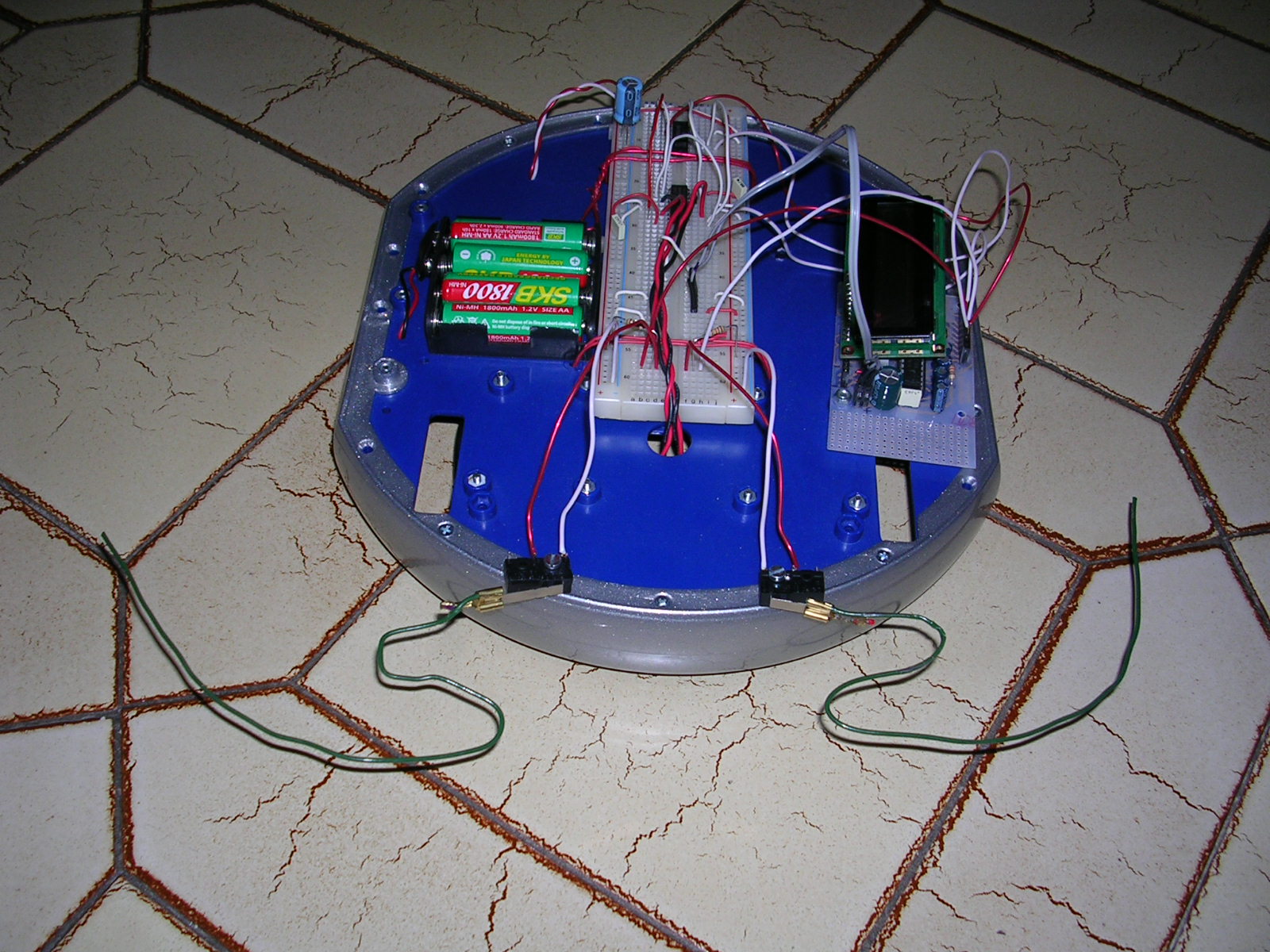
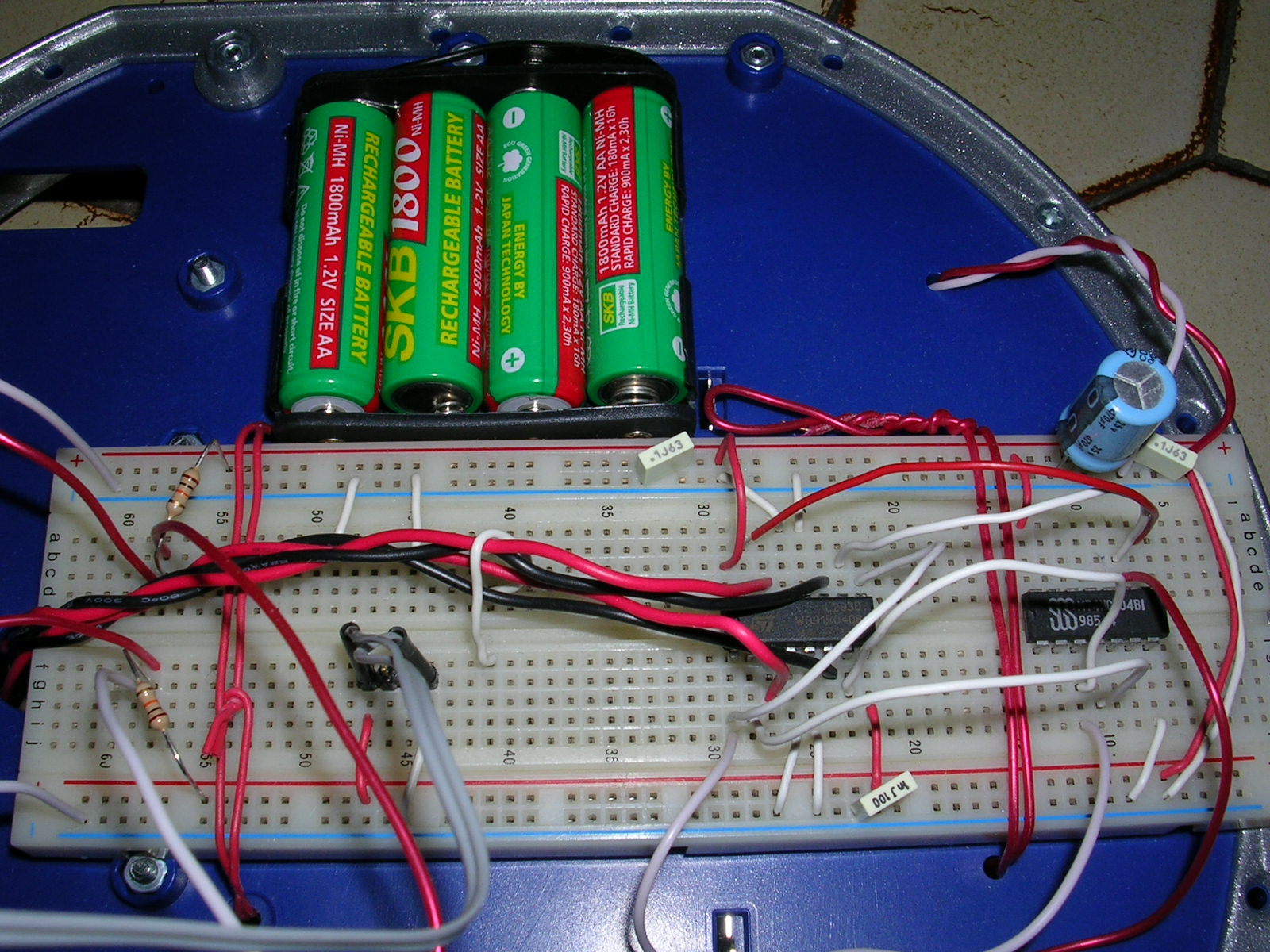
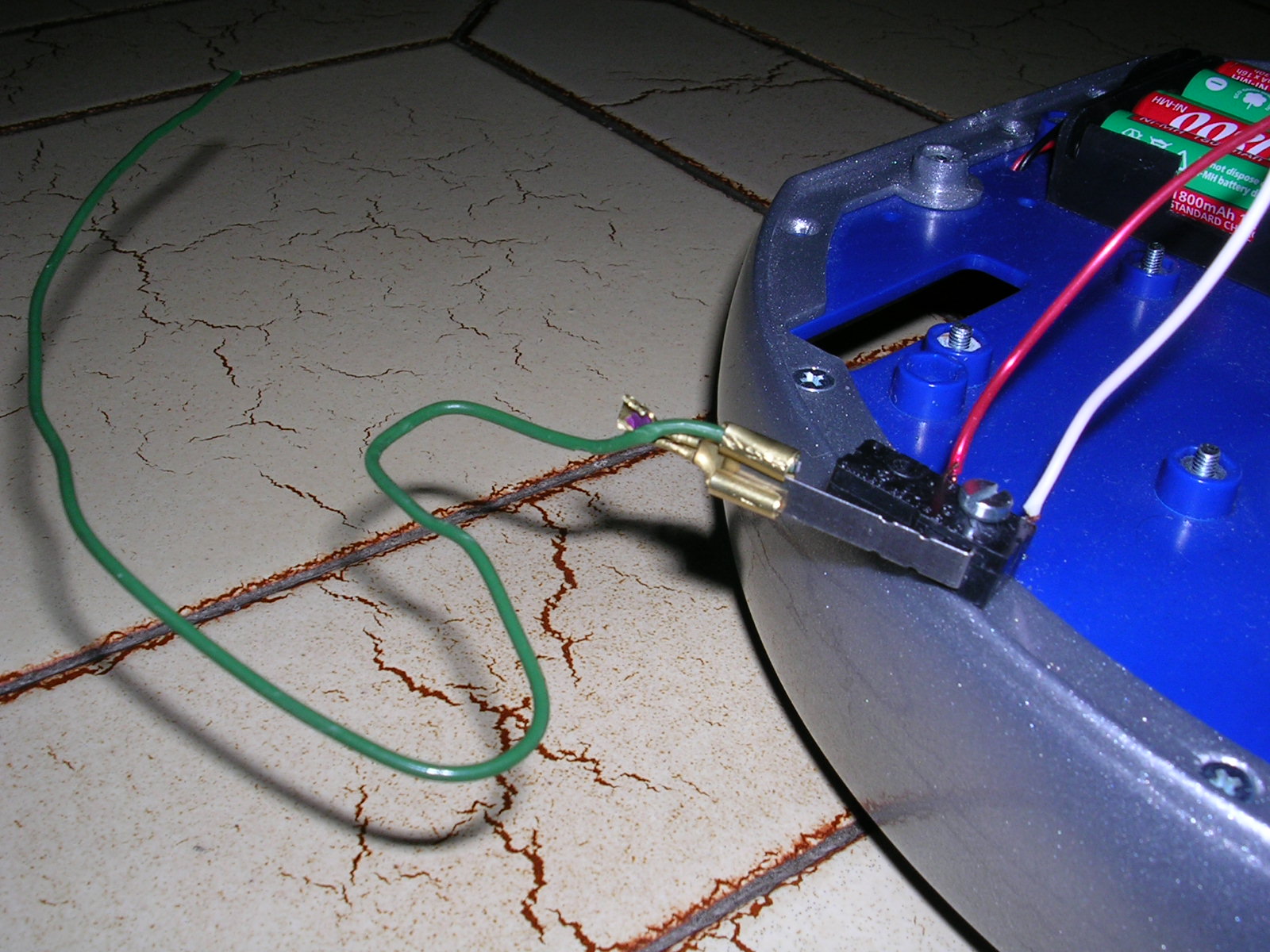
The circuit consists of a 628Board, the “brain” of the system, an H bridge made with L293D to drive the motors and two whiskers, which are nothing more than simple switches to avoid obstacles. The circuit is powered by 4 AA batteries, the ones I used are 1.2V rechargeable batteries, for a total of 4.8V this gives me the possibility to directly power all the electronics without the need to mount a stabilizer. Often the main problem to make a robot lies in the construction of the mechanics, in this case I used something ready, the basis of the first De Agostini robot, however in case you have difficulties now they are also on the market. The base I used is equipped with 2 motors with relative reduction and a swivel support wheel. I used the large base to mount the battery holder and a breadboard to build the H bridge circuit and the 628Board, but if you have a smaller base you can always think of a layered assembly. The whiskers are contact switches to which I fixed with fastons of the common iron wire as you can see in the photo, the operation of the mustache is that of a common switch, the PIC checks its status to understand if it is in contact with an obstacle or not.
Some pictures
The H Bridge
The motors are driven with a PWM signal, this allows for a simple acceleration, and not to require too much current from the batteries at the start. The best solution would have been 2 PWMs, but the PIC 16F628 only has one. The following diagram is the one relating to the circuit, it shows the indications of the connections to the 628Board.
The code
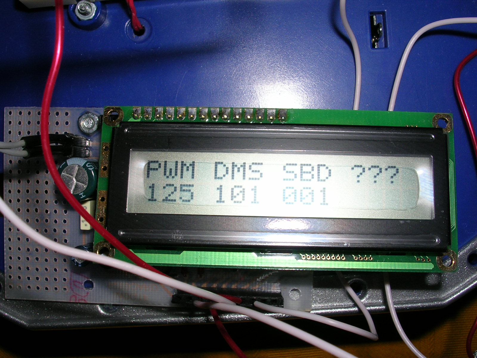
Let’s look at the main function code first. As usual, the registers for the operation of the ports are initialized first, then the functions are called to initialize the display. The function “lcd_puts (“ PWM DMS SBD ??? “);” it is used to print on the first line of the display the labels of variables that we will use to debug the robot. The values of these variables are printed under the labels in the second line, for example the PWM label indicates the variable that contains the value of the PWM generated by the PIC which varies from 0 to 255. To write these values under the labels, the function “lcd_put_uchar (value, row, column);”, where value is the variable to be displayed (unsigned char type), row is the row of the display to write on, and column is the column where the value is to be placed. Attention the value is always printed with 3 characters starting from the column position, for example if the variable to be displayed contains zero the result will be “000”. The next step is the initialization of the PIC for the generation of the PWM signal, the first register to be set is CCPR1L this register contains the 8 most significant bits for adjusting the duty-cycle, in this example only these bits will be used, leaving out the 2 less significant solely for simplicity of implementation. For the other registers it is possible to see the tutorial indicated above or the data sheet, for a more detailed explanation. Let’s now see the motors function (0,0,100); called before the infinite loop. This very crude function simply serves to generate an acceleration ramp for the motors, and set the direction in which they should turn. The values set for the initial duty cycle in the for cycle (see “duty” variable) and the initial check on the “rit_acc” variable are defined based on the characteristics of the motors used, it may be necessary to modify them, if the characteristics of the motors you use are different from the ones I used. However, by checking the data shown on the display, by trial and error you can easily find the most suitable value. In the infito loop that closes the program, the status of the whiskers is continuously checked and if one of these is pressed, the robot goes back for a period of time indicated in the motors function, then turns in the opposite direction to the pressed whisker and then resumes to move forward. Also in this case the timings may need to be modified according to the characteristics of your motors. At this point, all you have to do is have fun experimenting with your new robot.
/*
** Programma utilizzato per eseguire i test con la base mobile del robot DeAgostini
** Utilizza la scheda 628Board, comanda i motori con un solo segnale PWM e 2 segnali per la direzione
** Gestione di 2 baffi
**
** Porte usate per default:
** PORTB bit 0 Baffo DX (IN)
** PORTB bit 3 Uscita PWM del PIC (OUT)
** PORTB bit 4-7 collegato ai pin LCD data bit 4-7 (OUT)
** PORTA bit 0 collegato al pin LCD RS (OUT)
** PORTA bit 1 collegato al pin LCD EN (OUT)
** PORTA bit 2 collegato al Direzione motore SX (OUT)
** PORTA bit 3 collegato al Direzione motore DX (OUT)
** PORTA bit 4 Baffo SX (IN)
**
*/

#include <pic.h>
#include "delay.c"
#include "DMLCD2R.h"

__CONFIG (0x3F61); // Configurazione del programmatore

static bit DIR_MOT_SX   @ ((unsigned)&PORTA*8+2);
static bit DIR_MOT_DX   @ ((unsigned)&PORTA*8+3);
static bit BAFFO_SX     @ ((unsigned)&PORTA*8+4);
static bit BAFFO_DX     @ ((unsigned)&PORTB*8+0);

void motori(unsigned char dir_mot_dx, unsigned char dir_mot_sx, unsigned char rit_acc)
{
    unsigned char duty;

    CCPR1L=0;

    if(rit_acc>100)             // Se il ritoardo è maggiore di 100 lo fisso a 100
        rit_acc=100;

    DIR_MOT_SX=dir_mot_sx;      // Direzione Motore Sinistro
    DIR_MOT_DX=dir_mot_dx;      // Direzione Motore Destro

    // Visualizza la direzione dei motori DIR_MOT_SX|NULL|DIR_MOT_DX
    lcd_put_uchar(((dir_mot_sx * 100) + dir_mot_dx),1,4);

    /* Questo ciclo for permette una accelerazione pseudo esponenziale il
        valore iniziale del duty cycle è basato sui motori che ho utilizzato
        potrebbe essere necessario cambiarlo */
    for(duty=110;duty<255;duty++)
    {
        lcd_put_uchar(duty,1,0);
        CCPR1L=duty;
        if(rit_acc>1)
            rit_acc--;
        DelayMs(rit_acc);
    }
}

/********************************************************************************/

void main(void)
{
    CMCON=0x07;     // Disabilita i comparatori sulla PORTA
    PORTA=0x00;     // Azzera PORTA
    PORTB=0x00;     // Azzera PORTB
    TRISA=0b00010000;
    TRISB=0b00000001;

    lcd_init();     // INDISPENSABILE serve ad inizializzare l'LCD
    lcd_clear();    // Cancella il display

    /* Stampa sulla prima riga le etichette per il controllo
        dello stato delle varie periferiche */
    lcd_puts("PWM DMS SBD ???");

    /***** Int PWM *****/
    CCPR1L=0;       // Valore PWM
    PR2=0xFF;
    T2CON=0x04;
    CCP1CON=0x0C;
    /***** END Init PWM *****/

    motori(0,0,100);

    // Loop infinito
    for(;;)
    {
        if(BAFFO_SX==0)
        {
            // Visualizza lo stato dei baffi BAFFO_SX|NULL|BAFFO_DX
            lcd_put_uchar(100,1,8);
            motori(1,1,100);
            motori(1,0,60);
            motori(0,0,70);
            // Visualizza lo stato dei baffi BAFFO_SX|NULL|BAFFO_DX
            lcd_put_uchar(0,1,8);
        }

        if(BAFFO_DX==0)
        {
            // Visualizza lo stato dei baffi BAFFO_SX|NULL|BAFFO_DX
            lcd_put_uchar(1,1,8);
            motori(1,1,100);
            motori(0,1,60);
            motori(0,0,70);
            // Visualizza lo stato dei baffi BAFFO_SX|NULL|BAFFO_DX
            lcd_put_uchar(0,1,8);
        }
    }
}
Robot Zero in action
Just a short video showing it in action.